Project
I received a broken Panasonic YAGH unit for a GH4/GH4R camera.The description was that it simply failed at some point and was dead. The original owner has a second YAGH in operation, so I'm ruling out handling error.
Since the Audio part also did not work, I can rule out any ground loop or static electricity issue with the SDI ports as the cause.
If the SDI ports are broken, I'm still left with a good XLR audio preamp for my GH4. ;)
My educated guess is a burned protection diode/0 Ohm resistor/fuse in the power supply due to a power spike or ground loop.

Disassembly
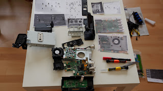
Don't start this disassembly unless you have
- a LOT of table space to lay out the bolts
- a means to print photos you made of each board/side/layer to put the bolts on
- I learned the hard way that putting the unit onto a photocopier does NOT produce good results
Use the photos I made to get a good understanding of how the different parts inside connect to disassemble them later.
You can have to disconnect the board with the 2 XLR audio connectors to physically separate "Main" and "Power" board.
You have to disconnect the front panel "SW-Audio" board from the "Main" board to to physically separate the elements
You have to remove the lower board "Main" with the SDI connectors to remove the plastic on top of the "Power" board.

Aparently you can reconnect things in a way to run the YAGH without any case and easily reachable contacts. Just the upper side of "Main" and lower side of "POWER" are blocked because they mate to each other.

What surprised me was, that the unit actually contains an micro-HDMI to HDMI cable and a full sized HDMI socket inside!
My guess is that this is to easily replace a broken cable but then again...you need to completely disasembly EVERYTHING to reach that cable.
Power supply

The unit accepts XLR power with
- 12V applied on Pin 4 and
- GND on pin 1.
- Pin 2+3 are not connected
- Rated for 11-17V (1.4A at 12V) -> 16.8V D-Tap power is fine but very near the top limit
Setup: I'm testing the unit with a DTap to XLR power adapter cable.
I could also use a lab power supply but attaching it would be difficult as the cables are very well insulated and leave no place where I could attach clamps.
Lessons learned: aparently you CAN insert a chinese D-Tap plug THE WRONG WAY without any resistance.
Found the problem? The Power board is not supplying power to any of the other board. The fuses are intact and there are no obviously burned capacitors or diodes that I could easily replace.
SDI out

- 1080p24/25/30 -> the same 1.5G SDI signal on all 4 outputs
- 1080p50/60 -> the same 3G SDI signal on output 1 and 2
- UHD at 24/2530fps or DCI 4K at 24fps ->4 FullHD segments as 1.5G SDI signals on each port
Audio board


They are then routed into the board "VJBB0F44" with 4 low noise amplifiers labeled "8202 304 JRC".
It also houses the Pogo pins to the large connector on the camera and a large connector to the main board.
Guesses:
My guess is, that this does all the audio pre-amp and hands these over to the camera.
It should also provide the volume level to the main board for display and get level information from the input board via the main board somehow.
All the other pins should just be routed through from the main board to the camera.
I fuether guess that if I supply this board with power and connect it to the GH4, it may work on it's own (with a fixed level value).
If the amplifiers are similar to the NJM8202, they should have a 15V power supply.
Keine Kommentare:
Kommentar veröffentlichen